An embedded System consists of an electronics hardware board (platform) and a software running on a specialized IC (Microcontroller or microprocessor). The specifically designed electronics hardware would have all the capability to control and monitor the specific application the product has to do. The software / firmware running on the microcontroller or processor will or tell (rhetorical only) this hardware, how / when to do each tasks to complete the product application.
Embedded System products are everywhere around you. Infact, in todays world, we are not able to live without an embedded system product. Just look around, your mobile phone, smart tv, microwave oven, washing machine, smart watch, fitness band, security surveillance camera, Inverter and the list continues. Hence the opportunity in embedded system is huge.
This is a quick practical learning series for those who would like to learn embedded system programming. There is no need of a hardware, the only requirement is a computer with internet access and a mind to put some efforts to learn. In this content, there won’t be much explanation on hardware design, instead we strictly focus on learning the programming side. I will skip some of the concepts especially related to hardware, microcontroller intentionally to keep this simple.
Readers are required to have a basic understanding of C programming.
Arduino is a microcontroller based development board for easy prototyping. In this series, we are using Arduino Uno (one of the available arduino boards). We have one excellent online platform where we can use Arduino and other electronics components to make some circuits, write code for our application and simulate its working, it is tinkercad from Autodesk.
Creating an account in Tinkercad
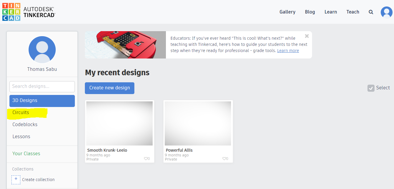
All you need is an email id. Click here to join tinkercad. Then click on create a personal account. Now you can sigup with your email. If you have a google account, can use it as well. Once the sign in process complete, you will get a window like below. From this window, we have to select the Circuits tab on the left side (I marked with yellow colour).
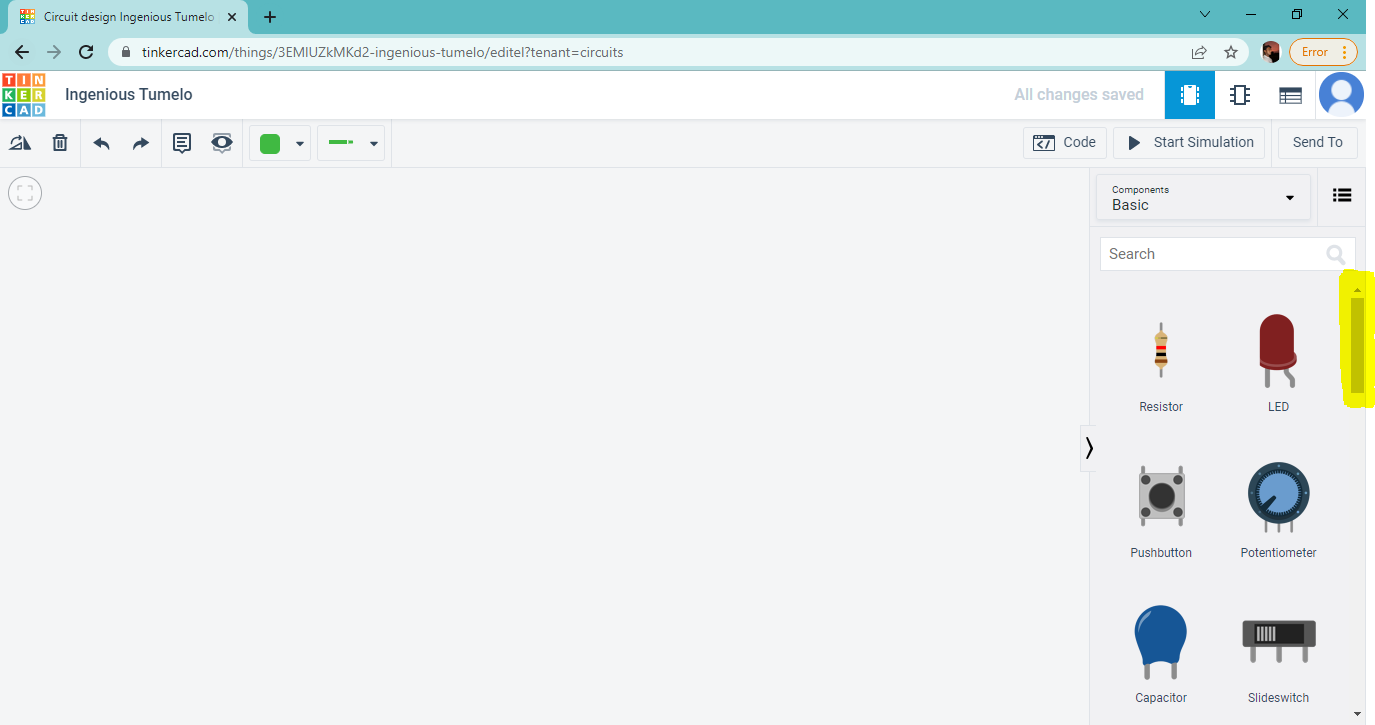
The circuit page contains lot of sample circuits done by other creators, but we are not interested in them. You can view a Create new Button on the top itself. Click on that and you are all set to draw your circuit and can view a window like below. On the right side you can view some electronic components and if you scroll down you can see the complete list, also you can see Arduino Uno R3.
A brief about Arduino Uno R3
Arduino Uno R3 is the third revision of Uno board. It is based on Atmel atmega328P microcontroller. Lets familiarize the board. As I mentioned earlier, we explain only few things and skip most of the details to make this simple for a beginner.
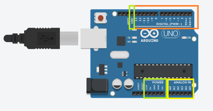
Important points on Power pins (See the pins marked in Green)
- Arduino Uno works on 5V.
- There are total three GND (ground) pins. One on top and two row on bottom row.
- 5V pin is where we will get 5V output. If we need to give 5V to any other components, we can connect 5V pin and GND pin to the other components
- There is an additional circuit inside the board, a low drop linear regulator (LDO) to give 3.3V output. So, if we have component which works on 3.3V, we can give power to them by wiring 3.3V and GND pins.
Important points on digital pins (See the pins marked with Orange)
- Every microcontroller have digital pins called GPIO (general purpose Input Output) pins through which many other components like led, buzzer, push buttons, ultrasonic sensor, relays, motors etc can be connected.
- Some of these pins have multiple functions (we will see this later).
- There are total of 14 digital input output pins marked from 0 to 13 (see top row).
- The specialty of digital GPIOs are, these pins can as either are INPUT pin or as OUTPUT pin. This means the same pin can be used to turn on an LED (output device) or reading the state of a push button (input device). The programmer has to tell Arduino, whether a particular pin has to act as INPUT pin or output pin.
- Another Specialty of digital GPIOs are, when these pin act as output pin, the output pin voltage can be 0V (LOW) or 5V (HIGH).
- When these pin act as an input pin, it can read HIGH (5V) or LOW (0V). I intentionally written HIGH as 5V and LOW as 0V, which is an ideal condition, but in actual it is a band of voltage.
Important points on ADC pins (see the pins marked in Yellow)
- There are total of 6 analog to digital converter input pins named as A0-A5.
- In default case, these pins can read voltage from 0V to 5V.
- We use these pins normally to read analog sensors like LM35 temperature sensor.
Programming Arduino
I have heard many times that programming in C is difficult, programing in python is difficult, the entire programming is difficult etc. But the truth is, if you can explain the solution of a problem in English (or any other language) to your friend or colleague, you are able to tell the same solution to your microprocessor or microcontroller. You have grammar in English and you have syntax in programming language. Based on your friends ability, you may change the explanation of a problem solution. Right? Like this, based on the hardware capability, you have to change the logic of your solution. If you can find the solution of a problem, you can tell that solution to any one, including your microcontroller. Programming is simple!
An Arduino program is called as a sketch. It is a subset of C/C++ and is consists of two blocks.
void setup()
{
}
void loop()
{
}
void setup() is the hardware initialization block. Inside the two curly braces, we have to write the initialization of the hardware features we are using in a particular program. As you can understand, the initialization has to be done only once. We will see what is the hardware initializations of each application while writing examples.
void loop() is a superloop; which means whatever we write inside this block will be executed for infinite times, it is a never ending loop. We have to write the main logic of the application inside this block.
Programming digital GPIO : Setting a pin as INPUT or OUTPUT
As we explained earlier, the programmer has to tell the microcontroller that a particular pin can act as an INPUT pin or n OUTPUT pin. In order to tell this to the microcontroller, there is one function, pinMode(). Lets explain it.
Syntax: pinMode(digital pin number, INPUT or OUTPUT );
pinMode function tells the microcontroller that the pin number mentioned inside the function is INPUT or OUTPUT.
Example 1: set digital pin 10 as output pin:
pinMode(10, OUTPUT);
Example 2: set digital pin 8 as input pin:
pinMode(8, INPUT);
You noticed a semicolumn at the end of each line, which is the termination in C /C++ language. Please ensure that you put termination semicolumn at the end of each line, otherwise you will get an error.
Controlling the OUTPUT voltage of a digital GPIO set as output
Once a pin is set as an output pin, we have to control the voltage at the output of the pin. It can be either HIGH (5V) or LOW (0V). Inorder to tell microcontroller that the voltage of a particular output pin is HIGH or LOW, there is one function; digitalWrite()
Syntax: digitalWrite(pin number, HIGH or LOW);
digitalWrite () function tells the microcontroller that the pin number mentioned in the function has to be HIGH or LOW. Provided condition is, you must make this pin as an output pin before the digital pin.
Example 1: making the output of digital pin 10 as HIGH
digitalWrite(10, HIGH);
Example 2: making the output of digital pin 8 as LOW
digitalWrite(8, LOW);
Application of digital GPIO pins
With digital GPIO pins, we can interface various digital input and output devices to the microcontroller. For eg;
- Connect an LED to the gpio and blink the led as per the programmers plan
- Connect a relay circuit and control a FAN or Bulb or any device in your home
- Connect a digital proximity sensor and turn on a buzzer when something comes under the proximity
- Connect a PIR sensor and turn on the lights through a relay when somebody enters your room
I can list down 100s of such simple applications. Now lets start developing a simple application and test it in tinkercad.
First Example: Blinking an LED
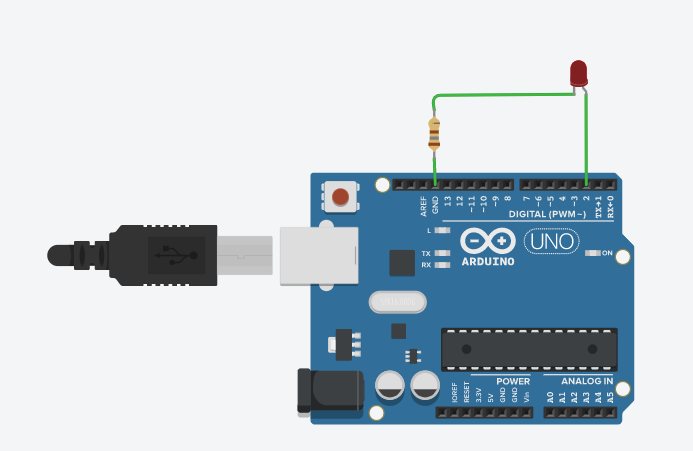
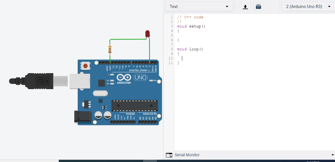
From the tinkercad components list we have seen earlier, drag Arduino Uno R3 to the schematic window on the left side. It is very simple. Click on Arduino Uno and drag it to the left side. Then drag one LED and on resistor to the window. Now wire the circuit like below. In order to draw wire, put your cursor on LED Anode (right pin, when you place the cursor on the top of the pin, the name of the pin gets displayed). The click on the anode pin, move the cursor to the Arduino pin2 and click on arduino pin2. That’s it, you can see the wire connection now. Similar to that do the remaining wiring. When you click on the resistor, you can see the option to change the resistor value. For this case, you make it 180 Ohm. Also, when you click on LED, you can view an option to change the colour. But now, let it be red. So our circuit is complete now. Lets write the code.
On the top right side of the schematic window, you can a button Code. Click on that and you will see a small window with lot of blocks. Infact, to develop an application you donot want to write the code, instead you can drag and build logic. But we are focussing on coding. In order to ge the coding window, from the drop down window, select Text instead of Blocks. Then a popup will come and ask you whether you want to continue, click on continue. And you can see the coding window. If you notice it, there is already some code written inside void setup and void loop. No need to worry, lets delete it to get a clean window as below.
Now lets understand our application. What we have to do is, connect one led to digital pin no 2. LED is an output device and inroder to turn on the led, the digital pin2 has to act as an OUTPUT pin. This is our hardware initialization. Once its done, we have to turn on the LED. After some time we have to turn off the led and after some time, we have to repeat these lines again.
After Some time, in programming we call it as a delay. There is one function to to make X milliseconds delay.
Syntax: delay(required time in milliseconds);
eg: delay(1000); This delay function creates a dealy of 1000 millisecond aka 1 second.
Now we are ready with our logic. Since its a simple logic, I am not drawing a flow chart or writing and algorithm.
Inside our void setup() block, we have to write our hardware initialization. It is making our pin no 2 (connected to led) as an output pin.
void setup()
{
pinMode(2, OUTPUT);
}
Now inside our void loop() block, write our logic. As we explained earlier, first we have to turn on led, wait for some time (one second now) then turn off led and wait for some time and repeat this sequence.
void loop()
{
digitalWrite(2, HIGH);
delay(1000);
digitalWrite(2, LOW);
delay(1000);
}

Once we complete the code, click on Start Simulation Button. And if everything in your code is correct, you can see that the LED is blinking. Try changing the delay and see the difference.
As I mentioned earlier, the termination at the end of each line is important. If you forget to put one, it will end up in error as below.
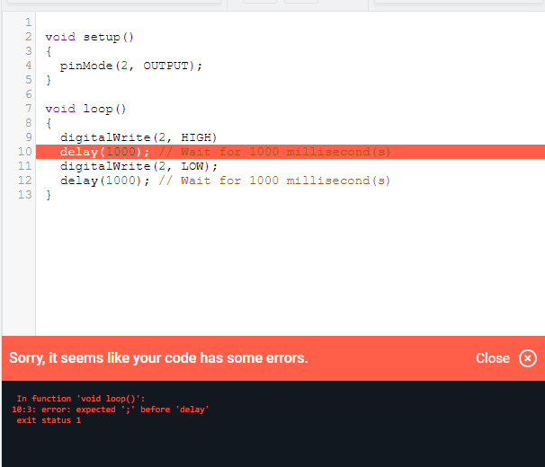
The above is a syntax error and the compiler tells you that there is one error. But some times all our syntax will be correct, but there might be logical error or some times there will be real world limitations.
For example, In this application, remove the second delay and see what is the result.

You may see the LED is not blinking, instead LED is ON always. Why is it so. Lets think about the speed at which the microcontroller is executing these lines. It would be in the order of microseconds only. So if we see the last line, the microcontroller turns off the led, immediately it turns on the led, maybe after (say) 20 microseconds. Actually the LED is blinking, but human eyes have a limitation. The Persistence of Vision, human eye cannot differentiate a change happening less that 1/16th of a second. So, Inorder to feel that LED is blinking, we must give a delay which is considerably greater than 1/16th of a second (62.5ms).
This is for today. In next part, we can do some more examples with digital pin as output.
Golden Rule in Programming
- Never write the program directly after you get the requirement. Prepare the program architecture or algorithm or a flow chart so that you are very clear on what to write and how is the program flow.
- Identify the bugs in program is an important skill. So, while learning, think of possible errors and try to make it and see what the compiler tells you about the error.
- If you writing a code for embedded system application, try to understand the hardware, its limitations and work environment. This will help a lot to avoid unexpected errors.