In this part we will see how we can set a digital GPIO pin as an INPUT pin and read the status of that pin, then we do few example.
As discussed in previous parts, inorder to set a particular pin as INPUT, we need to use pinMode( )
eg: in order to make pin no 12 as input pin, we have to write
pinMode(12,INPUT);
Once we set a particular pin as input, we may connect some component which will give a high / low voltage input at that particular pin, for eg, we can connect the output of a Passive Infra Red sensor (PIR) to the digital pin configured as input. In that case, our microcontroller need to read the status of the pin, whether it is HIGH or LOW and that status will be the output of the sensor. Inorder to read the status of a digital input pin, there is one function, digitalRead( )
Syntax: digitalRead(pin number);
Example, int stat = digitalRead(12);
when we call this function, first the processor go and check what is the status of that particular pin, whether it is LOW or HIGH, then the function will return either 1 or 0 corresponding to whether the pin is HIGH or LOW respectively.
For eg, assume we have connected a 5V to pin no 12 and we set pin no 12 as INPUT. Now when we execute the function,
digitalRead(12);
the processor checks the pin status and since it is 5V (that is HIGH), the function will return 1. As shown in first example, if required, we can store this returned status in a variable. So, that all about the theory part. Now we can do a simple experiment.
We can connect one LED and Slide switch to Arduino. What we have to do is, turn the LED on when the switch is in left position and turn the LED off, when the switch is in right position. I have drawn the circuit as below.
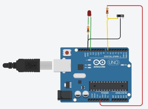
I have connected the LED to gpio 13 and switch to gpio 7. The common point of the switch gets connected to GND. So when the slide switch is in left position, GND gets connected to gpio 7. When the switch is moved to right position, we have to ensure that gpio 7 is HIGH, and hence we pulledup GPIO7 to 5V using a resistor.
Now on the logic part, we have to do two hardware initialization, LED pin (gpio 13) has to be set as OUTPUT, and Switch pin (gpio 7) has to be set as INPUT. This has to be done in void setup. Then in void loop, we have to check the status of Switch pin, if the pin is HIGH, this means switch is in Right position, and the LED has to be OFF and vice versa. So, I have written the code as follows.
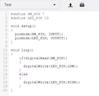
Its simple, and working fine. Note how I made the code readable, instead of giving pin nos directly at each function, have given a suitable name which made the code more readable.
Internal Pullup
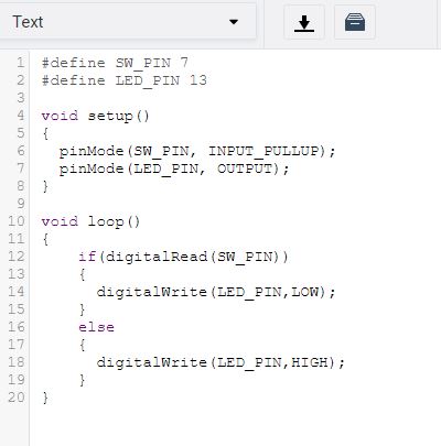
In most of the microcontrollers, for digital GPIO pins, there is an option for activating internal pullup. In Atmega328P also, there is such a feature and in arduino we can use it by changing the second argument in pinMode( ) function.
for example, inorder to set pin no 7 as input and activate its internal pullup, we have to write as follows.
pinMode(7, INPUT_PULLUP);
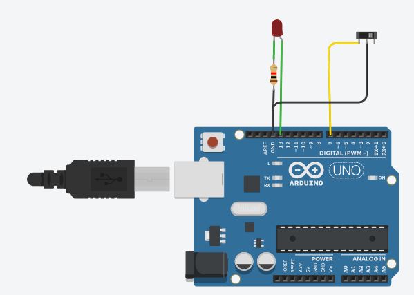
So, we can simplify the above application circuit as shown below.
and the code has only one change, rest remains exactly same, as below.
So, I hope you have now a fair idea on how to make one digital gpio pin as INPUT, read it status and the concept of internal pullup.
Note: If you would like to know what will happen if we use the above circuit which is not is having an external pullup and in code you forget to use internal pullup, try it and see. You will understand the importance of this.